
Recoil Design Considerations
Edge Dimensions Tang Removal |


Design Method
The ultimate consideration is to design an assembly that balances the tensile strength of the bolt material against the shear strength of the parent material. With insert lengths available in 1, 1 1/2, 2, 2 1/2, and 3 times the nominal thread diameters, there are engagement lengths available to produce an assembly thread system where the bolt will fail without damage to the parent material or thread. The bolt must be fully engaged along the entire length of the insert to obtain this position.Selection of the correct length insert can be determined from Table 1 referring to values for bolt ultimate strengths and parent material shear strengths. For intermediate strength value, use the next higher bolt tensile value or the next lower parent material shear strength.Assembly strength is a function of shear area and the shear strength of the parent material, tensile strength and cross sectional area of the bolt. Table 1 provides a recommendation of the nominal length of insert which should be selected for a parent material of a certain shear strength, so that when a bolt is used with defined tensile properties, tensile failure of the bolt should occur before the insert is stripped away from the material in which it was inserted.
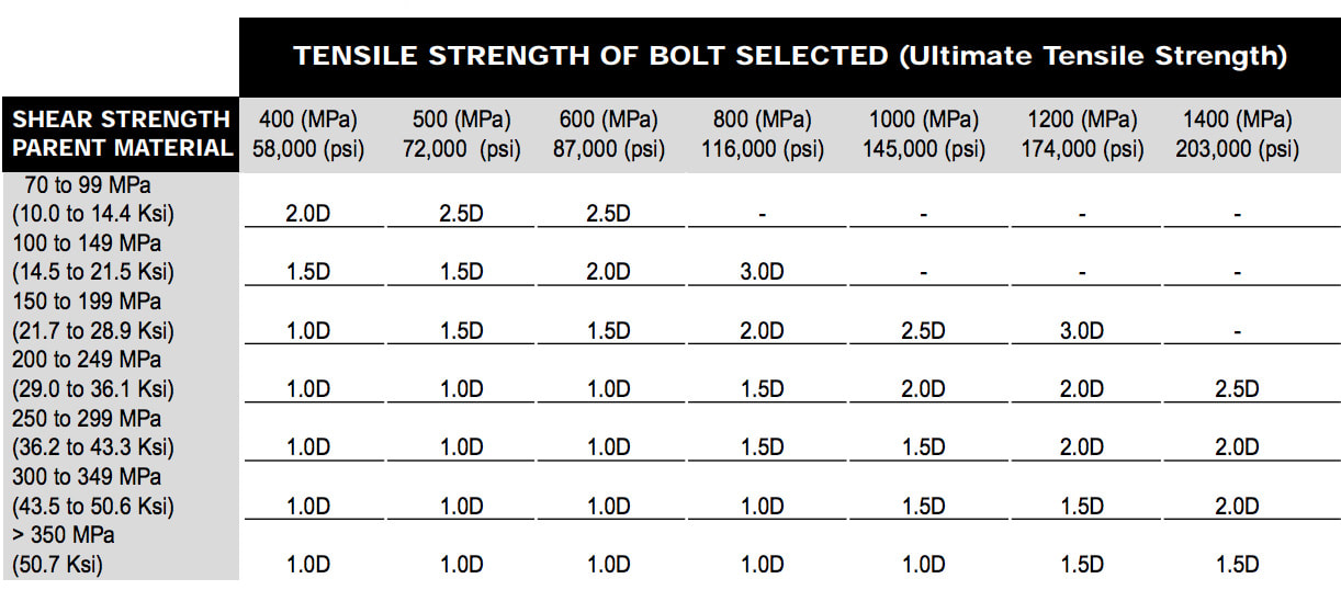
Note: Inserts are available in different lengths which are measured by the diameter of the thread. For example the length of a 3D insert would be three times the diameter. Note: Table 1 is for guidance only. It remains the responsibility of the user to ensure that the insert nominal length chosen is suitable for the particular application concerned.
Design Method
The following Procedure can be used to verify a joint design incorporating a wire thread insert. 1. Select size and strength of bolt to be used. (refer to table 2) 2. Determine tensile failure load of the selected bolt. 3. Determine shear strength of parent material for the installation of the insert. (refer to table 3) 4. Determine length of insert based on the shear strength capability if parent material. Note: Information in referring to joint strength is intended as a guide only. Engineering design configurations must be sought when exact calculations are required.
Design Example (Metric) Units | Design Example (Inch) Units |
STEP 1: Select Size and Strength of bolt to be used
|
Type Nominal Diameter Pitch Shear Strength |
M16 x 2.0, SHE Grade 8 16.0 mm 2.0 mm 1034 MPa (Refer Table 2) |
Type Nominal Diameter TPI Tensile Strength |
1/2″-13 UNC, Socket Head Cap Screw 0.500″ 13 181,000psi (Refer Table 2) |
|
Table 2 Strength, Bolt (Metric)
|
Table 2 Strength, Bolt (Inch)
|


Step Two: Determine tensile failure load of selected bolt
|
Min Thread Diameter Shear Area Tensile Failure Load |
13.797mm (handbook) 149.5mm2 (calculated)* 154.589kN (calculated)# |
Min Thread Diameter Shear Area Tensile Failure Load |
0.407″ (handbook) 0.130″2 (calculated)* 23,450 psi (calculated)# |
| *Area based on minor thread diameter. #Parent material shear strength must exceed this | *Area based on minor thread diameter. #Parent material shear strength must exceed this |
Step Two: Determine shear strength of parent material for the installation of the insert (refer Table 3)
|
Type Shear Strength |
2024 Wrought Aluminum, T64 temper 283 MPa (Refer Table 3) |
Type Shear Strength |
5083 Wrought Aluminum, annealed Condition 25,000 psi (Refer Table 3) |
|
Table 3 Shear Strength, Parent Material (Metric)
|
Table 3 ShearStrength, Parent Material (Inch)
|
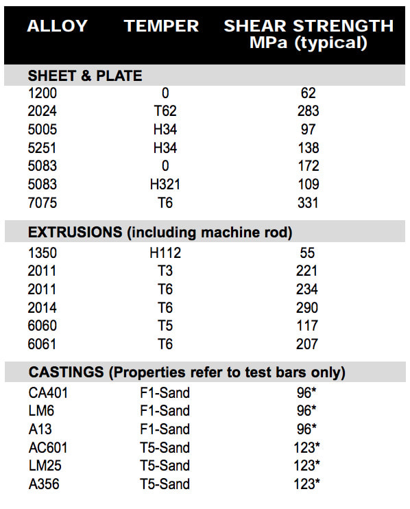

Shear strength of standard parent materials, (indication only refer supplier for specific properties) *Shear strength based on 60% of ultimate tensile strength.
Step Four: Determine the length of insert based on shear strength of parent material
|
Nominal Diameter Pitch Pitch Diameter (min) |
16.0 mm (Selected bolt) 2.0 mm 17.299mm (Refer Taped Hole Data) |
Nominal Diameter TPI Pitch Diameter (min) |
0.500″ (Selected bolt) 13 0.550″ (Refer Taped Hole Data) |
|
L= |
Tensile Strength of Bolt Shear Circumference Strength of Hole x Arbitrary Constant |
L= |
Tensile Strength of Bolt Shear Circumference Strength of Hole x Arbitrary Constant |
|
L = Length of fitted insert Arbitrary Constant = 0.5 (Based on shearing of the parent material occurring along the pitch diameter of the tapped hole) |
L = Length of fitted insert Arbitrary Constant = 1.085 (Based on shearing of the parent material occurring along the pitch diameter of the tapped hole) |
Conclusion: For this application a 16mm diameter bolt has been selected. Insert engagement of 20.2mm was calculated. The suitable diameter of the insert can be determined by dividing the length of the insert by the diameter of the bolt. For example: |
Conclusion: For this application a 1/2″ diameter bolt has been selected. Insert engagement of 1.085″ was calculated. The suitable diameter of the insert can be determined by dividing the length of the insert by the diameter of the bolt. |


|
|


The shaded area in the graphs indicates the region in which bolt failure will occur.
| Note: Inserts are available in standard lengths which are multiples of the diameter. For example an insert with a length of 1.5D will measure one and a half times as long as the diameter when installed. Note: The example above is an indication only. Engineering design configuration must be sought when exact calculations are required. |
|

Thread Identification And Drill Chart
Metric

*M10 X 1, M12 X 1.25, M14 X 1.25, M18 X 1.5 – popular spark plug sizes sizes above M24 available on request.
INCH
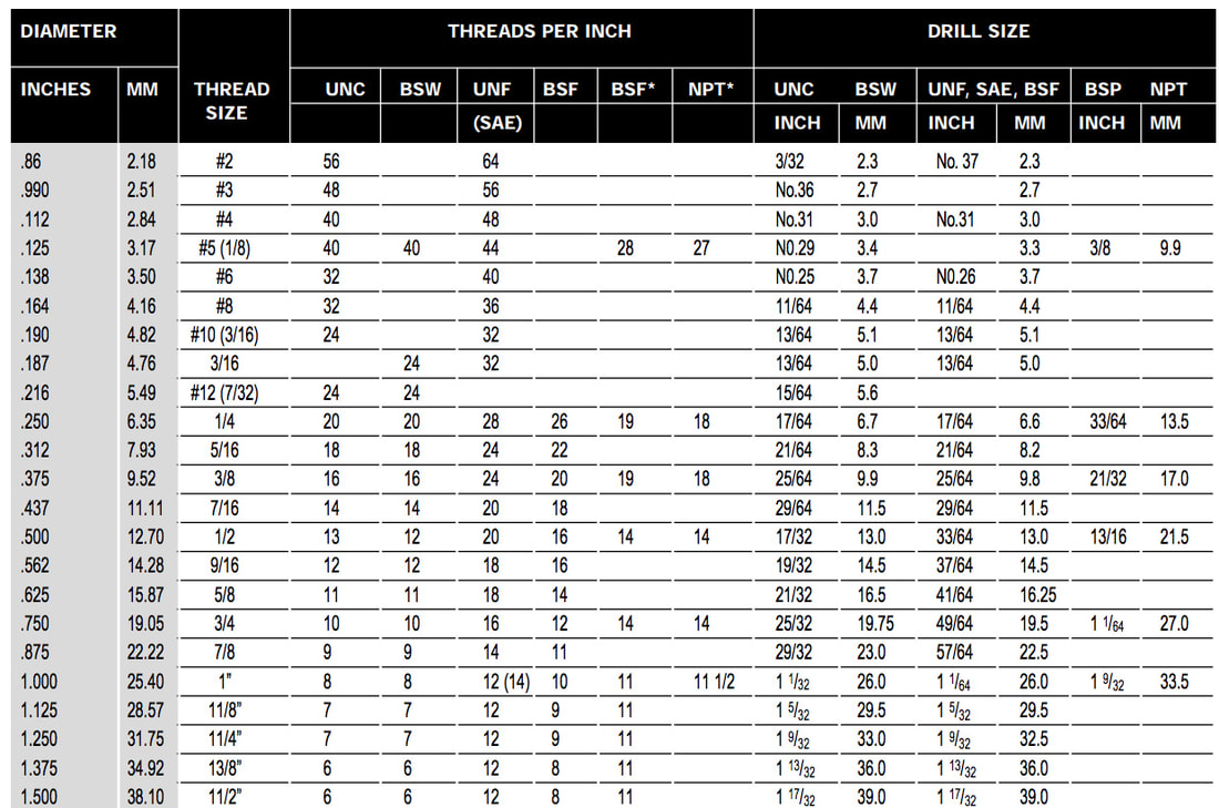
*Nominal diameters for BSP and NPT are not thread diameters but relate to the inside diameter of the pipe.
|
Screw Pitch Gauge It is critical that inserts match the tapped hole exactly as some inch and metric are very close but only one is exactly right. A screw pitch gauge is the perfect tool to identify exact TPI or pitch. The bolt diameter should be measured and matched to the closest size over, relating to the TPI or pitch of the thread.In general, major diameter of bolt or male thread will always be slightly less than the exact diameter listed in the thread identification and drill chart.
|
Drill Sizes Drill sizes are recommended only. The nearest standard size drill above or below is generally quite suitable for repairs and in many instances, drilling is not necessary for stripped holes. For precision tolerances, the thread identification and drill chart is an accurate guide, but final size depends on material and machining conditions.In practice BSW interchanges with UNC except at 3/16″ and 1/2″, SAE interchanges with UNF, except 1″ UNF – 12 TPI, SAE – 14 TPI. |

Thread Features

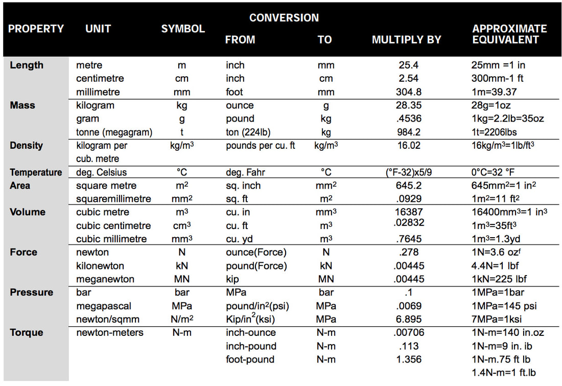
SI Units & Conversions for Characteristics of Mechanical Fasteners
Hardness Comparison Table
width=”200″

Relevant Insert Standards
|
Military Specifications MS122076 thru MS122275 MS124651 thru MS12444850 MS21209 MS33537 MIL-I-8846 MIL-STD-1312 MIL-L-8937 MIL-L-46010 MIL-T-21309 |
Title Insert, Corrosion Resistant, Helical Coil, Coarse Thread Insert, Corrosion Resistant, Helical Coil, Fine Thread Insert Screw Thread – Screw Locking Insert – Standard Dimensions, Assembly Inserts,Screw Thread, Helical Coil Fastener, Test Methods Lubricant, Solid Film, Heat Cured, Corrosion Inhibiting NATO Code No. S-1738 Lubricant, Solid Film, Heat Cures, Corrosion Inhibiting Tools For Inserting and Extracting Helical Coil Inserts |
|
Federal Specifications FED-STD-H28 QQ-A-250 QQ-P-35 QQ-P-416 QQ-Z-325TT-M-261 PP-H-1581 |
Title -Screw Thread Standards for Federal Service -General Specs for AL & AL Alloy, Plate & Sheet -Passivation Treatments for Corrosion Resisting Steel - Plating, Cadmium (Electrodeposited) -Plating, Zinc (Electrodeposited) – (Superseded by ASTM B633-85) – Methyl-Ethyl-Ketone (for use in organic coatings) – Shipment and storage of Packing for Hardware (fastener and related items) Packaging. |
|
SAE Specification MA1565 MA1567 MA3279 / MA3280 / MA3281 MA3329 / MA3330 / MA3331 AS 1370 AMS 2400 AMS 2402 AMS 2410 AMS 2411 AMS 2427 AMS 2460 AMS 2645 |
Title Inserts, Metric Screw Thread, Procurement Specification Inserts, metric, Standard Dimensions, Assembly Inserts, Screw thread, Metric, Free-Running Inserts, Screw Thread, Metric, Screw Locking Aerospace Standard – Metric Screw Threads MJ Profile Aerospace Material Standard for Cadmium Plating Aerospace Material Standard for Zinc Plating Electroplating Standard, Silver, Nickel Strike Electroplating Standard – Silver, High Temp. Applications Aluminum Plating, Ion Vapour Deposition Magnetic Particle Inspection Fluorescent Dye Penetrant Inspection |
|
AECMA Specifications (European Aerospace Standards) EN 2942 EN 2943 EN 2944EN 2945 EN 3044 EN 3542 | Title Insert, Screw Thread, Self Locking, (Inco x 750) SilverPlated |
|
SBAC Specifications AGS 3600 AGS 3700AS 6733 AS 8455 |
Title Insert, Screw thread, metric, screw locking, helical coil corrosion resistant steel DTD 734 cadmium plated Insert-screw thread, unified screw locking, helical coil, h.r. alloy BS HR 503 Source control drawing UNF Unplated UNF Cadmium plated |
|
LN Specifications LN 9039 LN 9499 |
Title Aerospace, wire thread inserts, assembly & special tools Aerospace, wire thread inserts, screw locking, assembly & special tools |
|
General Electric Specifications GE C9F1 GE N926 |
Title Wire Insert Stainless steel Wire Locking Inserts for temperatures up to 700 deg F |
|
DIN Specifications DIN 8140 |
Title Wire thread inserts for ISO metric screw threads – tapped holes for thread inserts thread tolerances. |
|
British Standard Whithworth Specifications BS 4377 BS 7751.1BS 7751.2BS 7752 BS 7753 | Title – Tapping of holes to receive wire thread inserts (ISO metric threads) |
Recoil manufacture to many standards and are available upon request.